Light Wiring Help

Joined
19 Dec 2015
Messages
2
Reaction score
0
Country
United Kingdom
Good morning,

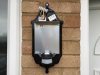
I am replacing an outside light (non PIR) with a new PIR one however, I am having a little difficulty with the differing electrical connections on the new light.

The attached pictures should help, but what I want to know is what goes where? There is also a switch just inside the front door.

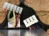
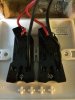
In the picture (I have put all of the wires into the connectors to make it simpler to view) there are two twin and earth cables coming out of the wall. The very left live is the only one with voltage going to it.

Many thanks for your
help.gif
 

Attachments

  • Wiring.jpg
    Wiring.jpg
    414 KB · Views: 256
  • Light.jpg
    Light.jpg
    337.1 KB · Views: 212
Sponsored Links
How was it wired before?
There are a number of ways this could be wired.
Did you wire it and find it blows the fuse/mcb?
Can you post a photo of the wiring in the switch?
 
Hi Freddo,
The previous light fitting only had two connectors and so the black wires went into each of these. The two red wires were just connected together using a connecting block and the earths weren't connected to anything.
I've not attempted to wire it yet as I have quite an old consumer unit that I have to replace the fuse wires if it blows, thus I didn't want to risk it and have the pain in the ar*e of replacing them!
Picture of the light switch is attached. The wires on the left are for the outside light and the ones on the right are for the hallway light. There is no voltage going through either of the outside light wires.
Hope this helps?
Many thanks
 

Attachments

  • Light Switch.jpg
    Light Switch.jpg
    97.7 KB · Views: 162
Connect the 2 reds into the permanant live terminal (you will have to see the light manual to find out which one this is (probably 1)
Connect the black wire from the left hand cable to the terminal marked N.
Connect the 2 earth wires to the terminal marked with the earth symbol.
Connect the black wire from the right cable to the switched live terminal (probably marked 2, but check the lights manual) This black wire should have a red sleeve on it or a little flag of red tape to identify it as switched live and not neutral.

This will allow the light to work via the built in sensor, and the switch inside when switched on will override the sensor so it is on all the time.

You should seal around where the cables enter the fitting with silicone to stop the rain and damp getting in to the electrical bits.
 
Last edited:
Sponsored Links
The two reds connect together in a loop and in separate connector to that that is on the new light.
The two green/yellows are connected at the earth terminal on the new lights.
You are now left with two blacks, one is a switch live, this comes live when the switch is closed/in the on position. The second is the neutral, at this point you need to identify which is which via either continuity test or voltage test. You then connect the switch live to the live terminal of new fitting and neutral to the neutral terminal.
The switch live once found, would be best identified via marking/sleeving.
 
The 2 reds need connecting together, but NOT to the light fitting. These do not have a loop terminal.

I have one of these lights.

The terminal block is also press fit.

The spare terminal is for a slave light
 

DIYnot Local

Staff member

If you need to find a tradesperson to get your job done, please try our local search below, or if you are doing it yourself you can find suppliers local to you.

Select the supplier or trade you require, enter your location to begin your search.


Are you a trade or supplier? You can create your listing free at DIYnot Local

 
Back
Top