Nest system CH working HW not....

Joined
21 Mar 2016
Messages
14
Reaction score
0
Country
United Kingdom
Hi,

Hope someone can assist with my difficulties in wiring the Nest 3rd Gen Thermostat.

I've managed to get the Nest installed in my existing thermostats place using the existing wiring wired into the Nest Heat link box. The heat link is powered up and plumbed in to the CH call and com, this works a treat in adjusting the heating.

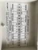
My only problem is now I can't seem to get the HW working with the Nest. I've attached the wiring diagram where my wiring from boiler, pumps and programmer.

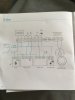
I've attached a screenshot of the wiring diagram for the "S-plan" setup that I've been following in the Nests instructions manual.

Any help will be greatly appreciated.

(This is also posted in the home automation section although after reading some post it seems I'd probably get a better response in this section so apologies about the duplication).

+++++++++++++++++++++++++++++
Duplicate removed
//www.diynot.com/diy/threads/forum-rules-general-info.19448/
++++++++++++++++++++++++++++++++
 

Attachments

  • image.jpeg
    image.jpeg
    123.5 KB · Views: 193
  • image.jpeg
    image.jpeg
    80 KB · Views: 163
Last edited by a moderator:
Sponsored Links
That picture of the lid of the wiring centre is of little use, since there is no way to know if your system has actually been wired like that, or what type of system you actually have.

However, for hot water the Nest device should be connected where the programmer was, i.e. the terminal marked HW ON.
For heating, it connects to the CH ON terminal, and a link is installed between the terminals that went to the old room thermostat.
Both programmer and old room thermostat are removed.
 
Yes the wiring is exactly the same as that diagram.

I've removed the Thermostat cabling and re-used this for the 12v feed from the T1 and T2 from the heat link.

To give the Nest heat link it's 240v I have used the feed from the programmer (worked with L in 9 (Htg on) with the programmer setting for heating switched on.

I have the 2 and 3 from the Nest heatlink in the respective terminals 2 and 3 marked CALL and COM on the wiring diagram, the heating works fine.

So now I just have to remove the cable going into HTG ON in terminal 9 and put the cable coming from the "CALL" which is terminal 5 on the heat link? Where would the COM (port 6 on the heat link) go then?
 
Here's a sketch for you. The motorised valves aren't shown for clarity, but they will be as per your photo. (4, 6 and 7 for heating) (8, 6 and 7 for water) Programmer wiring to be removed, because the Nest takes care of that function.

This assumes that terminal 11 marked 'L' is connected to a permanent live.

Wiring.jpg
 
Last edited:
Sponsored Links
Here's a sketch for you. The motorised valves aren't shown for clarity, but they will be as per your photo. (4, 6 and 7 for heating) (8, 6 and 7 for water) Programmer wiring to be removed, because the Nest takes care of that function.

This assumes that terminal 11 marked 'L' is connected to a permanent live.

View attachment 95929

Done as you said programmer wiring removed and wired as you advised. There is no wiring link between terminal 7 and 11 or 8 and 14 (only 8 to 7 and also 16).

Reading the bottom of the diagram it seems that the wiring links are replicating a "biflo system", would this make any difference?
 
'Biflo' = S plan

Thanks for confirming, so removing programmer wires (need to use the L and N from there to power heat link?) - Programmer is downstairs next to boiler see not in airing cupboard where hot water tank is.

Then once removed I need to remove 2 and 3 that go to Thermostat and use them for T1 and T2 to go down to existing thermostat location but connect the Nest there (this is complete and powered up no issue).

The thermostat is working for CH, now for HW where do I connect the call and com going to the Nest heat link?
 
The thermostat is working for CH, now for HW where do I connect the call and com going to the Nest heat link?

If you have a permanant live at terminal 11 in the wiring centre
This is the easiest way, that still allows all the wiring labels in the lid of the wiring centre to be correct (as the heatlink is only replacing the the programmer (from a wiring point of view)):
Put the wiring and links back to how it was before
Disconnect the wiring to the old programmer from the wiring centre
2 and 5 from heatlink to 11 (Permanent live) in wiring centre
3 from heat link to 9 (Heating on) on wiring centre
6 from heatlink to 10 (hot water on) on wiring centre
4 from heatlink to 8 (hot water off) on wiring centre
Disconnect room stat from wiring centre and use for T1,T2 (as you have already done)
Fit a link between 2 and 3 on wiring centre.

Stems diagram above is correct for an S plan system (which has 2 2port valves)
In a Y plan system (with a 3 port mid-position valve) the link from 11 to 7 in the diagram above will send a permanent live to the hot water off connection on the mid position valve, so hot water would never be available.

There's no permanent L from 11, there's a cable from there to a separate strip on the inside but this isn't connected to anything from there onwards. The only L I have is coming from 9 and 10 from the programmer downstairs (guessing I have to leave either CH or HW switched on at programmer and use permanent live from there?
 
ideally you would link one of the old programmers wires to live and move it to terminal 11. The other programmer wire would then be disconnected at both ends.

Do you not also have a wire from the programmer to terminal 8 in the wiring centre?
 
ideally you would link one of the old programmers wires to live and move it to terminal 11. The other programmer wire would then be disconnected at both ends.

Do you not also have a wire from the programmer to terminal 8 in the wiring centre?

Yes there was one going from terminal 8 but as this was from the programmer it has since been removed.

I will link the L from behind programmer now up stairs and connect to terminal 11. Where would the L for the heat link be connected to? Also 11?
 
Where would the L for the heat link be connected to? Also 11?
Yes.

This still applies:
4 from heatlink to 8 (hot water off) on wiring centre.
Done everything as above, power at heat link. Set Nest for 30 minute boost HW, nothing happens (hear the Nest click in), same with CH set temp to 5 degrees above current thermostat temp hear Nest click but nothing happens. Double checked all wiring, even pushed L through from behind programmer upstairs and connected through on 11, which is then connected to 2,5 and L on heat link.

Any other ideas? Probably easier to call out Nest installer you think...?
 
Well if the heat link clicks you must have power to 11, So there should also be power to the heat links 2 common connections (2+5). Points to check:
Is the hot water cylinder already up to temperature?
Has terminals 2 and 3 in the wiring centre been linked together?
Are the links set as per the instructions in the wiring centre lid?(for biflo)

If all the above has been done, do you have a multimeter? Can you post photos of the wiring centre and heatlink wiring, might be able to spot a wiring error quickly.
 

DIYnot Local

Staff member

If you need to find a tradesperson to get your job done, please try our local search below, or if you are doing it yourself you can find suppliers local to you.

Select the supplier or trade you require, enter your location to begin your search.


Are you a trade or supplier? You can create your listing free at DIYnot Local

 
Sponsored Links
Back
Top