A
Alarm
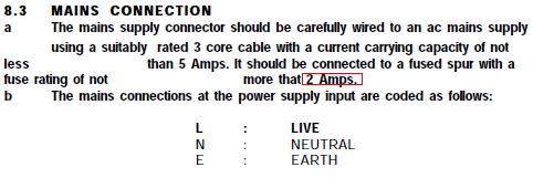
Before you power up have a good look at all your connections, make sure they are tight and no conductor showing. Especially on the mains side.
Power the panel mains first and then add the battery and enter the codes to silence and put into engineers. Then mains the PSU followed by the battery.
Close all lids and take out of engineers, you should have time and date showing. No tampers.
If you have its trace back time.
Once they are all clear program the system and do a walk test.
From the sound of it you might need a hand if your using all the SCB`s or you could seriously cheese off the neighbours.
Then take a load test of the panel and PSU. In both standby and alarm. This will see if you have overloaded anything, also give you standby times with the correct equation. (Although you probably dont want/need the standby times).
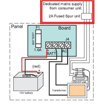
Use 3amp fuses in the spur (s) feeding the panel/psu.
Label the cables for future reference, it is very handy.
Also good practice to check and record the transformer output voltages, battery charging rates and DC outputs. Again for future reference. There are a few more checks we do but for your situation those should be fine..............oops an important one with your meter set to AC put the test probes on the mains earth and DC + and see what is recorded. Ideally the reading should be 1.2VAC or less.
Power the panel mains first and then add the battery and enter the codes to silence and put into engineers. Then mains the PSU followed by the battery.
Close all lids and take out of engineers, you should have time and date showing. No tampers.
If you have its trace back time.
Once they are all clear program the system and do a walk test.
From the sound of it you might need a hand if your using all the SCB`s or you could seriously cheese off the neighbours.
Then take a load test of the panel and PSU. In both standby and alarm. This will see if you have overloaded anything, also give you standby times with the correct equation. (Although you probably dont want/need the standby times).
Use 3amp fuses in the spur (s) feeding the panel/psu.
Label the cables for future reference, it is very handy.
Also good practice to check and record the transformer output voltages, battery charging rates and DC outputs. Again for future reference. There are a few more checks we do but for your situation those should be fine..............oops an important one with your meter set to AC put the test probes on the mains earth and DC + and see what is recorded. Ideally the reading should be 1.2VAC or less.