Timer board

Joined
12 Jan 2008
Messages
8,763
Reaction score
1,015
Location
Essex
Country
United Kingdom
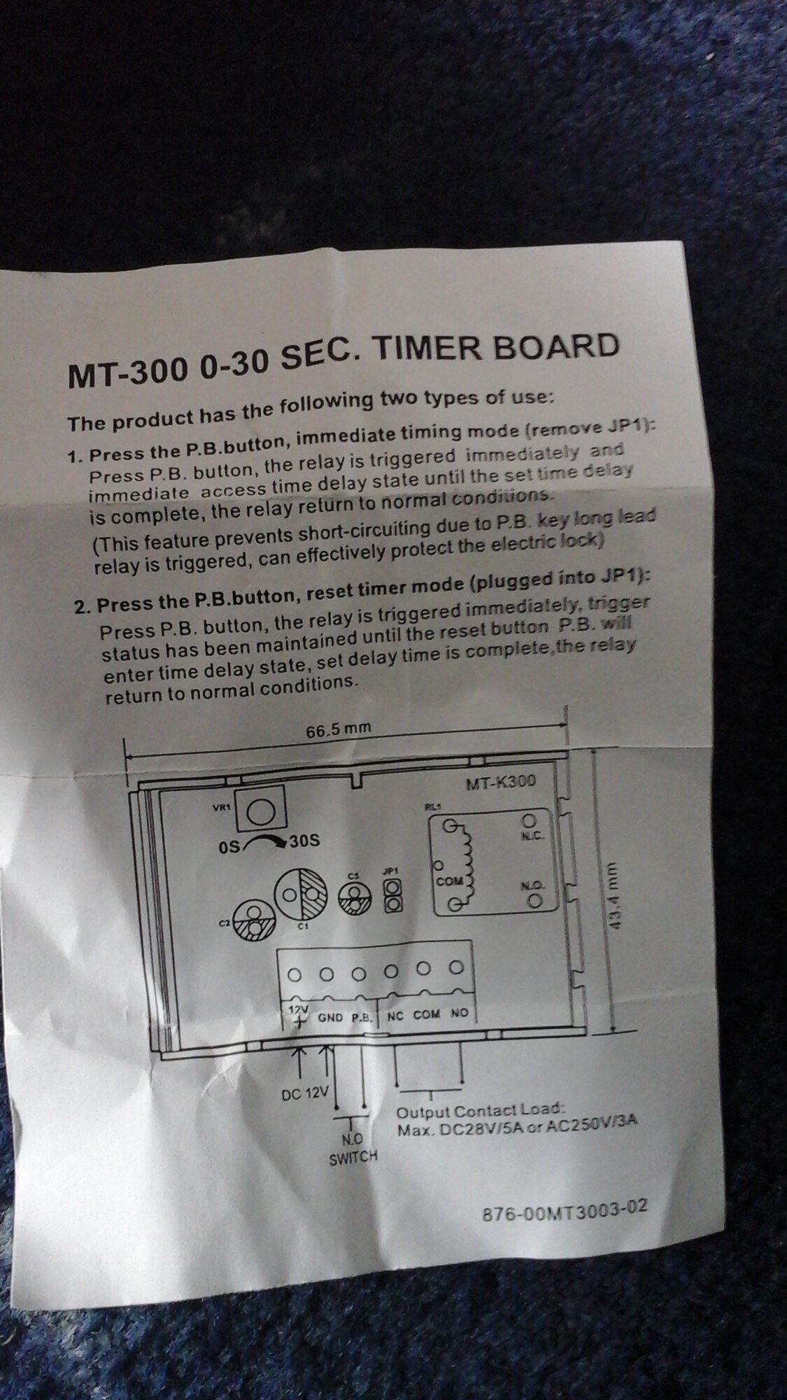
Bought from RS, basically to add to an existing gate maglock to allow more time for access.
However think i am ok with the wiring, but a bit lost regarding the Jumper position and what they are saying the difference between 1, and 2,
Any help appreciated
 
Sponsored Links
I think it's saying that if the jumper is removed then as soon as you hit the button the relay is energised and the timer starts counting down,
and if the jumper is present the timer only starts counting down once the button is released.
 
My first thoughts too, i assume option 1 prevents someone jamming the button in and hence leaving the gate open
30 seconds is ample time so will likely try that option
 
Sponsored Links
It doesn't mention the type of load the relay can handle so you might want to connect a hefty diode back to front across the contacts to prolong the life.
 
It doesn't mention the type of load the relay can handle so you might want to connect a hefty diode back to front across the contacts to prolong the life.
I seem to recall doing that once years ago on an old solenoid lock, what does it do stop the the contacts arcing or something, This is for a small 12 volt Dc maglock, do you think it would need a diode, If so i would have to order one and return at a later date.
Heres the timer on the Rs site

https://uk.rs-online.com/web/p/acce...MkWd-ZfkA0THhQtCOmxoCDlMQAvD_BwE&gclsrc=aw.ds
 
When the relay contacts open the current that flows through the solenoid coil needs to decay and if there isn't a path (say via a diode) arcing across the contacts is the result.
With a small solenoid I wouldn't worry...those modules are cheap enough and it looks like a standard easily obtainable relay.

 
It doesn't mention the type of load the relay can handle so you might want to connect a hefty diode back to front across the contacts to prolong the life.

the load that is on the sheet ? 5 amp 28v dc or 3amp 240v
Anyway most decent make mag locks have built in suppression
 
Indeed, although Rocky does not need the 400V PIV of a 4004, it would do no harm.

Kind Regards, John
Thanks John, Gasguru suggested putting the Diode across the contacts, but Google seems to show them across the coil.
Sparkymarka suggests the mag lock may have built in surpression which looking at ones on Google does seem likely.

So bit lost to be honest, where I put the Diode.

I cannot access the coil and do not really want to start soldering it so
Could i go across + and pb
or
Across the contacts
Com and N/C
 
A8F5B79C-7625-44F5-BDD9-9DC597BC72B7.png
It goes across the lock ….
 
Thanks John, Gasguru suggested putting the Diode across the contacts, but Google seems to show them across the coil.
Across the coil would be the norm. It's the 'back emf' across the coil which can damage contacts etc. Putting a diode across the contacts would send that voltage/current 'somewhere else', where I imagine it might possibly damage electronics.

Kind Regards, John
 

DIYnot Local

Staff member

If you need to find a tradesperson to get your job done, please try our local search below, or if you are doing it yourself you can find suppliers local to you.

Select the supplier or trade you require, enter your location to begin your search.


Are you a trade or supplier? You can create your listing free at DIYnot Local

 
Sponsored Links
Back
Top