
- Joined
- 6 Oct 2010
- Messages
- 126
- Reaction score
- 4
- Country

Hi everyone!
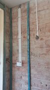
We have been slowly renovating our hall and landing walls and ceilings - back from brick and lath the past two years and had some new electrics put in before plastering up.
Our electrician is young, slightly arrogant but suitably qualified and made a bit of a hash job of channeling out brick for cables to run (a lot of lime mortar was shaken out of bricks along the bottom of the 1925 walls which needed repairing and he left a right mess everytime he came round - 3hr clean up job) but otherwise he seemed to have done the jobs we'd listed in a written agreement - of adding new sockets and altering/adding lights. So we paid him and the rest is history.
We finally got around to wiring up the wall lights I'd chosen the other week after 2 years since starting and the wire work till then was just pushed back into the plaster from which it came out.
I had the electrician back round and he made me feel totally stupid for even asking what wire we had to pull out to connect up to what, as the wall lights are on a loop with their own switch but no seperate breaker at the RCD.
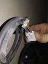
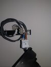
There are two grey cables coming out each hole in the wall (loop) and he said just connect live and live from each, neutral and neutral from each and block off the earth as it's not needed for wall lights.
So my Mr did that and was confident in his work. But not one light turns on!
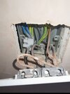
We checked they were connected at the switches - taking off the fascia's and they are. Checked the RCD unit. All fine there. Bulbs that work an' all.
I've asked the electrician to come back and see what's wrong and he tried helping via sending photos back and forth but sounds like he is planning on charging us to actually sort them out.
We already paid for the first fixing 2 years ago and haven't been in a position to test any lights on these wires at any point (he didn't either) due to the place not being plastered and no lights bought.
Any ideas why they might not work?
So you think we should pay for him to sort them out?
If we have done something daft and missed an obvious thing then we're fine paying but shouldn't they just work, having followed his instructions to 2nd fix the light fittings ourselves, of which all are new IKEA lights and none work? We even tried a spare old ceiling light fitting and no joy.
I'm really worried he'll have to channel the wires back out the plaster board and lime plaster on one wall and lift new carpets upstairs which we've recently had fitted!
We have been slowly renovating our hall and landing walls and ceilings - back from brick and lath the past two years and had some new electrics put in before plastering up.
Our electrician is young, slightly arrogant but suitably qualified and made a bit of a hash job of channeling out brick for cables to run (a lot of lime mortar was shaken out of bricks along the bottom of the 1925 walls which needed repairing and he left a right mess everytime he came round - 3hr clean up job) but otherwise he seemed to have done the jobs we'd listed in a written agreement - of adding new sockets and altering/adding lights. So we paid him and the rest is history.
We finally got around to wiring up the wall lights I'd chosen the other week after 2 years since starting and the wire work till then was just pushed back into the plaster from which it came out.
I had the electrician back round and he made me feel totally stupid for even asking what wire we had to pull out to connect up to what, as the wall lights are on a loop with their own switch but no seperate breaker at the RCD.
There are two grey cables coming out each hole in the wall (loop) and he said just connect live and live from each, neutral and neutral from each and block off the earth as it's not needed for wall lights.
So my Mr did that and was confident in his work. But not one light turns on!
We checked they were connected at the switches - taking off the fascia's and they are. Checked the RCD unit. All fine there. Bulbs that work an' all.
I've asked the electrician to come back and see what's wrong and he tried helping via sending photos back and forth but sounds like he is planning on charging us to actually sort them out.
We already paid for the first fixing 2 years ago and haven't been in a position to test any lights on these wires at any point (he didn't either) due to the place not being plastered and no lights bought.
Any ideas why they might not work?
So you think we should pay for him to sort them out?
If we have done something daft and missed an obvious thing then we're fine paying but shouldn't they just work, having followed his instructions to 2nd fix the light fittings ourselves, of which all are new IKEA lights and none work? We even tried a spare old ceiling light fitting and no joy.
I'm really worried he'll have to channel the wires back out the plaster board and lime plaster on one wall and lift new carpets upstairs which we've recently had fitted!
Attachments
-
 IMG-20220823-WA0000.jpeg267.9 KB · Views: 260
 -
 Screenshot_20230502_151158.jpg165.1 KB · Views: 258
 -
 Screenshot_20230502_151234.jpg88.8 KB · Views: 254
 -
 Screenshot_20230502_151245.jpg149.8 KB · Views: 221
 -
 Screenshot_20230502_151253.jpg76.9 KB · Views: 233
 -
 Screenshot_20230502_151305.jpg174.1 KB · Views: 211
 -
 Screenshot_20230502_151311_com.whatsapp.jpg143.7 KB · Views: 242


