• Looking for a smarter way to manage your heating this winter? We’ve been testing the new Aqara Radiator Thermostat W600 to see how quiet, accurate and easy it is to use around the home. Click here read our review.

Connecting Hive Thermostat to Ideal Boiler

Joined
25 Jan 2025
Messages
11
Reaction score
5
Country
United Kingdom
Hello, so as above really, I'm looking to connect my my Hive thermostat to my Ideal boiler but I'm a little confused at this point and keen to try and get some help if possible?

So, when I moved in our thermostat is an Ideal digital thermostat and we've now decided to change it to a Hive system and last night I've gone to get it all connected.

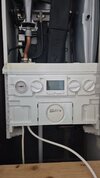
This is the original setup below.

Snapchat-1258236935.jpg


I followed this cable at the top and it goes to this box
20250125_084144.jpg


which also has a mains cable going to it as you can see and the direct other side of the wall is a boiler switch. I disconnect all of these cables above in the first image and connect the new Hive system using a 5 core cable into the room stat, live, neutral and eart ports however as soon as I disconnect the above original cable the boiler would not switch on and surely I still need that switched on for Hive to work? thanks!

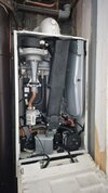
so now I wonder, am I meant to disconnect this or should this be left connected? I tried it with it still connected and I connect my Hive 5 core cable into the room stat/mains live, neutral and earth however my ideal thermostat was still working and activating the boiler and I know I need to disconnect that for Hive to work..

Sorry if this is all a bit stupid just keen to do it myself and save the money that I really cant afford. Thank you!
 
So ho many LNE did you have at the boiler after Hive was fitted? Seems you may have only had one set? Also, a lot of Ideal boilers should be checked for safety afterwards as the cover sometimes forms part of the combustion circuit/room seal.
 
So ho many LNE did you have at the boiler after Hive was fitted? Seems you may have only had one set? Also, a lot of Ideal boilers should be checked for safety afterwards as the cover sometimes forms part of the combustion circuit/room seal.

Hello, so I fit the Hive myself last night, I had all of the 5 core connected in the ports below and then into the Hive receiver. Pics below are how it looked once finished however the ideal thermostat was still working

20250124_202136.jpg

Snapchat-1577180613.jpg


So all cables were matched to where they should be

Blue cable - Neutral to Neutral
Brown - Live to live
Earth - Earth (but now I've seen online Hive doesnt need to be earthed as is double insulated)
Grey -In Room stat port/other end port 1 on receiver
Black - In Room stat also/other end port 3 on receiver
 
. I disconnect all of these cables above in the first image and connect the new Hive system using a 5 core cable into the room stat, live, neutral and eart ports however as soon as I disconnect the above original cable the boiler would not switch on and surely I still need that switched on for Hive to work?
That cable is the incoming supply that powers the boiler - it needs to remain connected.
However, this is exactly the cable that would need to be safely isolated, before attempting any wiring to the boiler - not knowing that, could potentially have been disastrous.

so I fit the Hive myself last night, I had all of the 5 core connected in the ports below and then into the Hive receiver. Pics below are how it looked once finished
Your wiring of the Hive appears correct, although there is a bit too much copper showing around the end of the grey wire at the boiler - this needs to be clamped further into the terminal.
The green/yellow earth wire should still be connected to the earth terminal on the Hive backplate, even though the Hive is double insulated.

however my ideal thermostat was still working and activating the boiler and I know I need to disconnect that for Hive to work..
The Ideal thermostat does need to be disconnected, or bridged out - is it a wireless stat with a receiver built into the front panel of the boiler? Can you post a picture?
 
That cable is the incoming supply that powers the boiler - it needs to remain connected.
However, this is exactly the cable that would need to be safely isolated, before attempting any wiring to the boiler - not knowing that, could potentially have been disastrous.


Your wiring of the Hive appears correct, although there is a bit too much copper showing around the end of the grey wire at the boiler - this needs to be clamped further into the terminal.
The green/yellow earth wire should still be connected to the earth terminal on the Hive backplate, even though the Hive is double insulated.


The Ideal thermostat does need to be disconnected, or bridged out - is it a wireless stat with a receiver built into the front panel of the boiler? Can you post a picture?
Hello,
Thanks so much for your replies!

So, the incoming supply I will keep connected, it is reconnected now and working.

In regards, to the copper showing, it is clamped and doesn't pull out but regardless, do I need to shorten it so there isn't much showing as if a lot is showing can it cause issues? I will also reconnect the earth :)

This is the ideal thermostat we have and has always worked but I cannot locate a receiver anywhere.
Snapchat-357027735.jpg

All I can find in terms of a box within the boiler area is this and the other side of this is the boiler switch and like you say, shouldn't be touched
20250125_084144.jpg
 
Here we are, thanks :)
You’ll need to remove that receiver in the front, as I don’t see a manual mode. It may need a blanking plate. As I said in my earlier post, that particular boiler, the burner seal is porous so safety checking can be critical.
 
You’ll need to remove that receiver in the front, as I don’t see a manual mode. It may need a blanking plate. As I said in my earlier post, that particular boiler, the burner seal is porous so safety checking can be critical.
Excellent, thanks for the info!
So I'll connect the earth again in receiver and rewire the boiler as I originally did here

20250124_202136.jpg


and so the receiver is the part on the front that says 'signal' and has all of the lights on? Will get the rewiring done and then look at removing that. Take it a flathead in those slots will get it out? In terms of being porous also, is there anything I should do to prepare before taking out this receiver other than turning boiler switch off? thanks!
 
so the receiver is the part on the front that says 'signal' and has all of the lights on? Will get the rewiring done and then look at removing that. Take it a flathead in those slots will get it out? In terms of being porous also, is there anything I should do to prepare before taking out this receiver
The receiver should prise out from the front panel...

Screenshot_20250125_104710_Adobe Acrobat.jpg

Somewhere, hopefully, you should find a small plug link (labelled 2 above).
This would plug into the connection left by the receiver.
If you can't find it, it can be ordered in.
For the moment, simply keep the ideal thermostat turned up to maximum. The Hive should take over.

In regards, to the copper showing, it is clamped and doesn't pull out but regardless, do I need to shorten it so there isn't much showing as if a lot is showing can it cause issues?
With that much copper showing, there is the potential for stray strands to cause a short - it's always best to reduce the amount of copper showing to a minimum.
 
You’ll need to remove that receiver in the front, as I don’t see a manual mode. It may need a blanking plate. As I said in my earlier post, that particular boiler, the burner seal is porous so safety checking can Attach filesbe critical.
and also I'm meant to take the red loop link out aren't I and then wire in the Hive cables (in this case black and grey) into those two room stat ports like I originally did here on the second picture?
Snapchat-1258236935.jpg


20250124_202136.jpg
 
The receiver should prise out from the front panel...

View attachment 370624
Somewhere, hopefully, you should find a small plug link (labelled 2 above).
This would plug into the connection left by the receiver.
If you can't find it, it can be ordered in.
For the moment, simply keep the ideal thermostat turned up to maximum. The Hive should take over.


With that much copper showing, there is the potential for stray strands to cause a short - it's always best to reduce the amount of copper showing to a minimum.
Thank you very much for that!

Is there any reason to keep it in place? as happy to remove it but I dont have a blanking plate yet so is it best to wait until I have a blanking plate?
Also, could you please check my comment on here just now, is that wiring correct with red link being taken out and then Hive wired in like I did? thank you both so much honestly this has been stressing me for a while!
 
Also, could you please check my comment on here just now, is that wiring correct with red link being taken out and then Hive wired in like I did?
Your wiring of the Hive appears correct


Is there any reason to keep it in place? as happy to remove it but I dont have a blanking plate yet so is it best to wait until I have a blanking plate?
You can keep the receiver in place if you wanted.
The important point, is that for the Hive to fully take over from your Ideal stat, the link plug shown above, needs to be inserted into the boiler connector, instead of the receiver plug.
As above, keep the Ideal stat set to its maximum, to give Hive control.
Thanks again!
So I've unplugged the receiver and can see where number 2 the link plug needs to go. I have a link wire but it's not in a plug so I'll need to buy one of them then but in the meantime I will do as you say and keep the receiver plugged in, turns old thermostat high and try the Hive.
Will get to that now :D

I take it this is the correct part?

 
Last edited:
I take it this is the correct part?
Did you take note of the number of pins that were on the plug for the receiver?
The one in your link has 8 pins, whereas yours may have 3?
The number depends mostly on the age of the boiler.
What is it's model number?
 

If you need to find a tradesperson to get your job done, please try our local search below, or if you are doing it yourself you can find suppliers local to you.

Select the supplier or trade you require, enter your location to begin your search.


Are you a trade or supplier? You can create your listing free at DIYnot Local

 
Back
Top