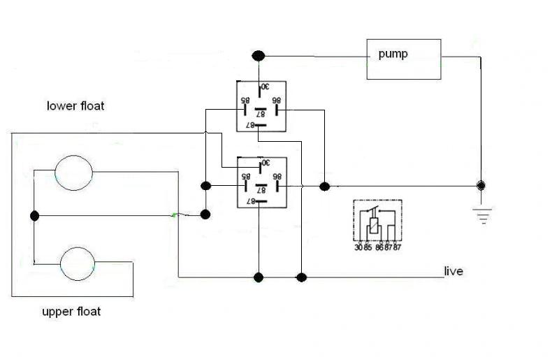
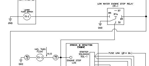
Have fitted the new and old float switches to the mixer; wired it all up following ericmans schematic
Turned the drain valve tap on by half, with the pump switch on its been pumping water as it should with the lower switch switching the pump on and the upper switch switching the pump off with out blowing ever switches
Infect I let it run like that until it flattened the battery
To answer ban-all-sheds question.
It was ericmans schematic that got me going and with out that I would probably still be ****ing in the wind
So I take my hat off to ericman if I could find it
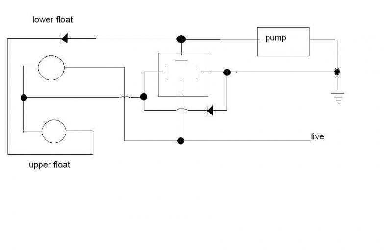
Ban-all-sheds idear that he posted, with all due respects was a bit gobbled de guke and did not explain how I should go about the business
Or are you just trying to claim gratitude for ericmans success
Well thank you for your input ban-all-sheds
White is normally infused non ignition live and blue with trace is head lights and blue on own often is supply to trailer live a caravan so with not more info I would say split charging supply!
Nope its American wiring so the white is normaly earth and blue normally live
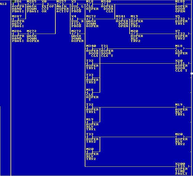
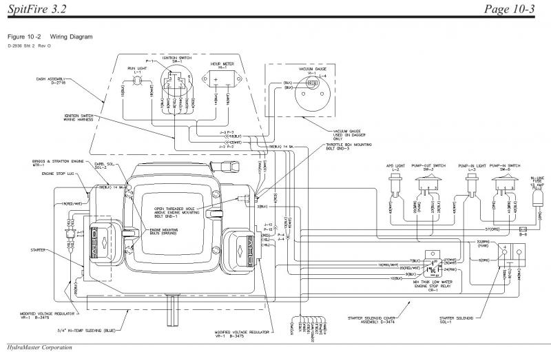
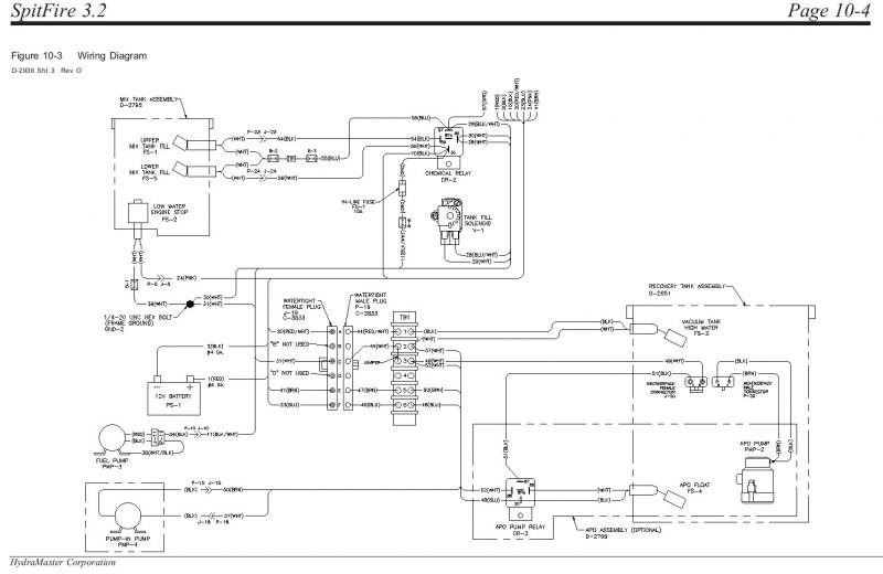
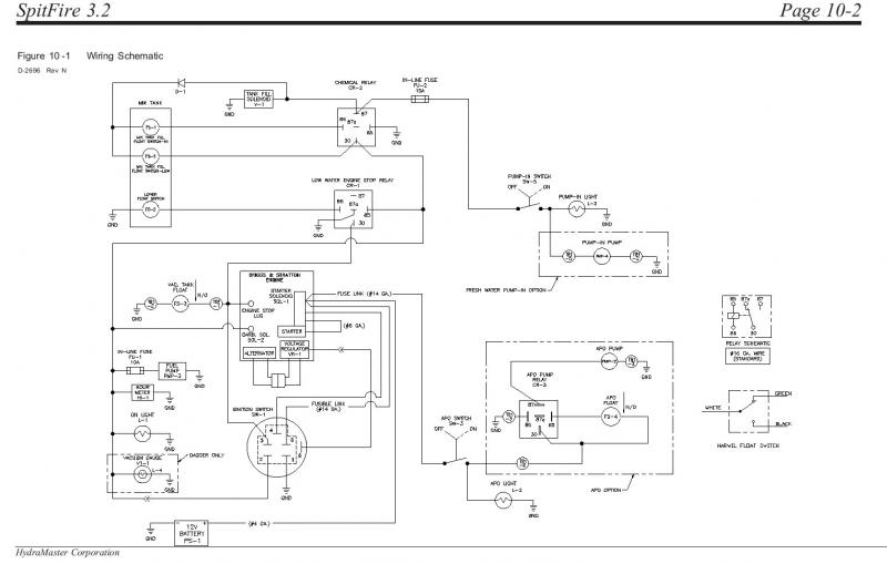
More info is needed so hears the full schematic
as you can see it’s the same schematic as the original for the other
But look at the chemical solenoid they don’t match up
I just wanted to know what the b2 and b3 boxes wear rely just for pice of mind if I had missed something off of my wiring before that might of been the problem
Thanks
James