Worcester 32cdi and hive

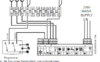
There are two options available. When new, the Greenstar is supplied with a hard wired link between a permanent live and the preheat function allowing the ECO button to work as described. The installer has the option of removing the link and wiring it to the hot water channel of a two channel programmer instead. If this has been done, the ECO button will only work when the programmer (ie Hive HW) is set to be on (which simulates the hard wired link being present). I'm guessing it isn't 'on' and that's why the boiler display is letting you know that it's waiting for the programmer to turn it on.

When HW is enabled on hive, it still doesn't preheat, and still displays ECO+clock
 
Sponsored Links
If you are electrically competent and can do this safely, you could remove the Hive and look at the wires connected to its backplate behind, and even make a modification by way of a test.

The Dual Channel Hive terminals are:

Hive.JPG


If the Hive has been connected to the boilers Hot Water control there will be a wire in terminal (3) 'Hot Water On'. If there is and you were to move that wire to terminal (L) that would then simulate the link at the boiler being put back in place. If the ECO button still doesn't work then, you will know that the problem is not with the Hive.

EDIT.
Initially, an easier test would be to have only the hot water switched 'on' at the Hive and look for code 201 as per the below:

abc.JPG
 
Last edited:
If you are electrically competent and can do this safely, you could remove the Hive and look at the wires connected to its backplate behind, and even make a modification by way of a test.

The Dual Channel Hive terminals are:

View attachment 253505

If the Hive has been connected to the boilers Hot Water control there will be a wire in terminal (3) 'Hot Water On'. If there is and you were to move that wire to terminal (L) that would then simulate the link at the boiler being put back in place. If the ECO button still doesn't work then, you will know that the problem is not with the Hive.

EDIT.
Initially, an easier test would be to have only the hot water switched 'on' at the Hive and look for code 201 as per the below:

View attachment 253509

Seems my black (and earth) wires aren't connected to anything. Photo attached.
 

Attachments

  • PXL_20211208_174838413.MP.jpg
    PXL_20211208_174838413.MP.jpg
    201.2 KB · Views: 58
Sponsored Links
Seems my black (and earth) wires aren't connected to anything. Photo attached.
That’s just lazy, the earth tether is right there! Black needn’t be connected as you have a combi boiler, so you only need heating on (4).
 
Hive is double insulated so it doesn't need an earth connection, the screw is called an earth tether / parking terminal. It's is just there to keep it safely out of the way. And the black wire isn't used so shouldn't be connected to anything anyway. The terminals that are used look secure enough, but as has been said the cable should be secured to stop the wires being pulled out. But, to be honest, most I've seen with bottom cable entry are not secured.

Anyway the thing is that Hive terminal 3 is not connected, so it's not controlling the DHW function.

My guess then is that the installer disabled the preheat by removing the link, but didn't connect it to the Hive.
 
Last edited:
Hive is double insulated so it doesn't need an earth connection, the screw is called an earth parking terminal. It's is just there to keep it safely out of the way. And the black wire isn't used so shouldn't be connected to anything anyway. The terminals that are used look secure enough, but as has been said the cable should be secured to stop the wires being pulled out. But, to be honest, most I've seen with bottom cable entry are not secured.

Anyway the thing is that Hive terminal 3 is not connected, so it's not controlling the DHW function.

My guess then is that the installer disabled the preheat by removing the link, but didn't connect it to the Hive.
Ok thanks, how to I enable the link? Is it easy enough to do? Thanks by the way, you've been really helpful.
 
The link is shown marked with the * in the diagram from the boiler manual that I have below, but you might want to check the manual supplied with your boiler to make sure it is the same. The link connects L to the LR (Live Return) with the tap symbol. I suspect that you may possibly find that the other end of the black wire is in LR, but hasn't been connected to the Hive.

Capture.JPG


Please note that if you have to open up the room sealed compartment of the boiler to access these terminals, you shouldn't attempt to do this. With some boilers you do, with some you don't have to. Unfortunately I don't know every boiler well enough to know if this is the case or not for you. Opening this compartment should only be done by a RGI so that they can perform the necessary safety checks to make sure it is properly sealed up again afterwards. One of the guys on here that is familiar with your specific boiler may be able to give you a definitive answer.
 
The link is shown marked with the * in the diagram from the boiler manual that I have below, but you might want to check the manual supplied with your boiler to make sure it is the same. The link connects L to the LR (Live Return) with the tap symbol. I suspect that you may possibly find that the other end of the black wire is in LR, but hasn't been connected to the Hive.

View attachment 253619

Please note that if you have to open up the room sealed compartment of the boiler to access these terminals, you shouldn't attempt to do this. With some boilers you do, with some you don't have to. Unfortunately I don't know every boiler well enough to know if this is the case or not for you. Opening this compartment should only be done by a RGI so that they can perform the necessary safety checks to make sure it is properly sealed up again afterwards. One of the guys on here that is familiar with your specific boiler may be able to give you a definitive answer.

Attachment called IAC is the photo of where the wiring is, so I need to remove the "installer access cover". I think I should manage that? All attachments here are for my specific boiler.

I think I'd be able to do it so for clarification, if I want the system to ignore the hive it should look like the diagram named "Install" attached?

I think mine will likely be looking like the attachment called "current", but without the connection being present in the programmer?

Cheers.
 

Attachments

  • IAC.jpg
    IAC.jpg
    69.9 KB · Views: 58
  • Install.PNG
    Install.PNG
    57.2 KB · Views: 56
  • Current.PNG
    Current.PNG
    42.5 KB · Views: 62
The "install" diagram you posted has the same connections shown as the diagram I have.

The only difference is that I deleted the other link shown, because your boiler will have the link between L and LR for the heating removed and the yellow wire from the Hive terminal 4 will be in there instead, as @CBW said earlier.

You have only mentioned one Hive, the diagram you posted called 'Current' says at the bottom it's for a system with 2 Room Thermostats and one Timer! So, if you only have one Hive it will have no significance for your installation.
 
Last edited:

DIYnot Local

Staff member

If you need to find a tradesperson to get your job done, please try our local search below, or if you are doing it yourself you can find suppliers local to you.

Select the supplier or trade you require, enter your location to begin your search.


Are you a trade or supplier? You can create your listing free at DIYnot Local

 
Sponsored Links
Back
Top