needless to say, such situations are beyond my experience, but I still don't see how it relates to 'the three neutral terminals' on a meter, and what one would connect them to (if no neutral were available0 - and, as I said, if a neutral (one neutral) were available, then I don't see why one would need (or 'know what to do with!) three neutral terminals on the meter.With bigger systems there are often different arrangements. I know it's deviating from the sort of system we are considering - but consider metering on the 11KV part of the system where there are just 3 wires feeding a substation, the only way to record usage is to measure the current and voltage of each phase individually. Admittedly one will not be using a straightforward meter we are accustomed to but the format remains the same by using current transformers on each phase conductor and a voltage transformer across two phases. Commonly down to say 20A and 110V
Sorry if I'm being dimn!
Kind Regards, John
")


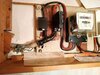
 ... A piccie of the inside of the doorbell transformer unit.