Problem wiring float switches

Joined
16 Jan 2009
Messages
119
Reaction score
0
Country
United Kingdom
This is my first post hear so first I would like to say hi

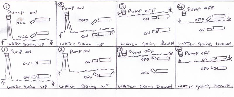
I have 2 Float switches that operate a ‘pump in pump’ for a mixer tank on a 12V DC circuit.
The Lower float switch turns the pump on and the upper float switch turns the pump off as can be seen in the hand draw diagram attached

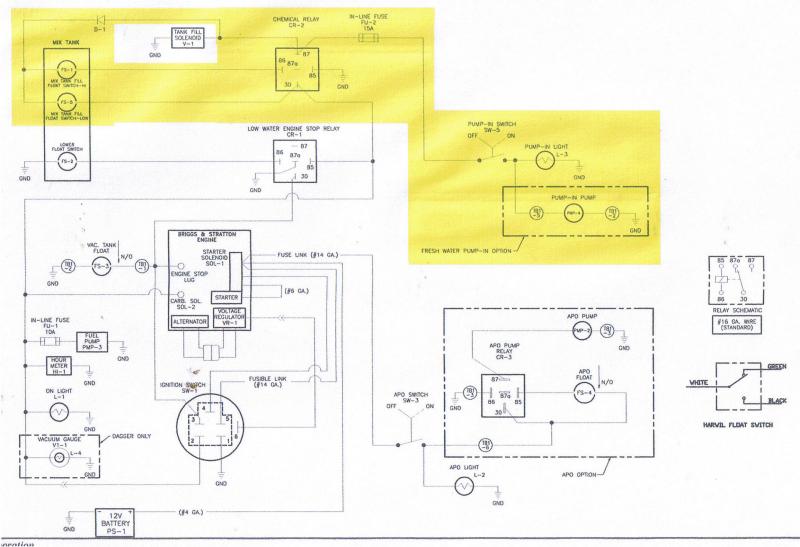
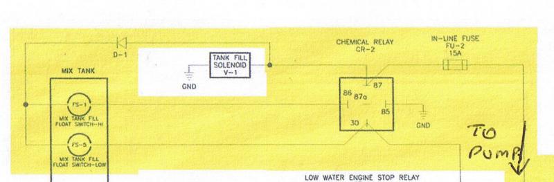
The problem is the float switches will only handle about 0.5 of an AMP and the pump has a load of 15 Amps; so they need to go through a relay which can be seen in the wiring schematic highlighted in yellow attached.
I have wired this up as seen in the schematic swapping the pump for a light bulb and the bottom sequence show in the hand drawn diagram works
But when I use the pump, the bottom float switch welds/fuses together and the pump will not turn off

Dose anyone know how to fix this problem

PS. There is no ‘Tank fill solenoid’ or ‘diode’ between FS-1 (upper float switch) and terminal 87 on the relay; as can be seen in the schematic which is not high lighted in yellow

Thanks

James


Sponsored Links
why have you got two float switches rather than one ?

what are you trying to do with the bottom one ?
 
Have you ommitted the diode D1 as this could cause the problem?
 
Sponsored Links
I don't follow - diode D1 should only allow the current to flow on terminal 87 side of the relay back to the coil, it should only allow the current required to drive the relay coil to flow through the float switches.
At no time should the 15A to the agitator pump flow through the float switches as the diode will stop this.
 
Thank you very much everyone

I have now gone and brought some diodes and fited one and the switch is now holding 15AMP

Spark123 I'm from Cumbria as well
 
I have had the floats switches switching on and off the pump as show in the above sequence working fine
Until now; I think the bottom float switch welded/arched together again and the top switch would not turn off completely (I think) only switch half off if you know what I mean

Because the bottom switch has welded together I can only come to the conclusion that the full 5 amps from the pump has traveled from port 87 to the lower switch without the diode stopping the full load and from port 30 from live to the other end/wire on float switch

As I have done a little research tonight and found that a diode is not for reducing the amperage only something to allow an electric current to pass in one direction and to block the current in the opposite direction
Please see this link
http://en.wikipedia.org/wiki/Diode

The original float switches designed for the machine are ‘Harwil float switches’
http://www.harwil.com/102/Q12DS-Install.htm
are designed for (I think) a switching current of 15 amps and the switches I have employed at the moment are rated at a switching current of 0.5 amps

Now I think what I need is some kind of amperage dropper to take the pump load from 5 amps to 0.5 amps to the switches
Anyone knows of an amperage dropper box I can buy or some think so cheep as a diode-resistor-capacitor……….

Thanks

James
 
no one ever said diodes drop current.

You will have to get a couple of relays.
Float switches will operate the relays, relays will operate the pump.

you will need relays that can carry the pump current, you may have to opt for contactors (big versions of relays)
 
Now I think what I need is some kind of amperage dropper to take the pump load from 5 amps to 0.5 amps to the switches
Anyone knows of an amperage dropper box I can buy or some think so cheep as a diode-resistor-capacitor……….
Oh - even cheaper than that.

All you need to drop the current is a resistor.

Of course, if you drop the current flowing to 0.5A the pump won't work, but that won't matter, will it, as long as the switches are OK?
 
The diode is an essential part of the design. As has already been pointed out, without the diode in place, the float switches carry the full starting current of the motor for the time between the switch contacts closing and the relay operating.

It might be possible to replace the diode with a resistor if a value can be selected that will allow sufficient current to flow to hold the relay operated and the current flowing to both the motor and relay coil is limited to what the switch contacts can handle, bearing in mind both motor and relay appear (to the switch contacts) to be connected in parallel.

If the tank fill solenoid was fitted, it may shunt back EMF from the motor slowing down after the switches open and the relay releases, so adding a resistor in it's place may give the switch contacts an easier life.

On occasions, even the back EMF from the collapsing magnetic field in relay coils can be enough to cause a 'splash' at switch contacts, so adding capacitors across the float switch contacts may improve their life expectancy, in the same way as car ignition 'points' have a capacitor fitted across them.

Another alternative may be to replace the relay with a double pole relay. One pole to service the pump motor, and t'other to provide the hold path when the lower switch is broken.

Maybe just fitting the diode is the simplest solution.....
 
It may be worth fitting a contactor adjacent to the pump.

Move the wire that goes to the pump from the pump and connect to the coil of the contactor. The other side of the coil connect to ground.

The contactor operates when the system requires the pump to run.

Take a new feed via a fuse from the battery to a contact on the contactor. Connect the other side of this contact to the motor.

When the contactor operates the pump gets a direct feed from the battery.

Advantage is the control circuit no longer has to switch power. This will prolong the life of the relays.

With a lower resistance connection to the battery the pump should run up to speed faster therefore saving power and wear on the motor during the period of high current before operating speed is reached.
 
This would normally be done with a contactor wired like any normal motor starter.
The main thing is it needs to latch on and you can't easy do that with car type relays.
Easy way would be to go for a relay with two or more sets of contacts. If you want to use car relays then a caravan charging relay will do the job these have one set of contacts to charge battery and another set to run fridge which can be used for latch.
level-switch.bmp
should show how one contact used to latch leaving second to do what you want.
 
Just fit the diode! It is there for the purpose of ensuring the upper limit switch does not try to power the pump, solenoid etc.
 

DIYnot Local

Staff member

If you need to find a tradesperson to get your job done, please try our local search below, or if you are doing it yourself you can find suppliers local to you.

Select the supplier or trade you require, enter your location to begin your search.


Are you a trade or supplier? You can create your listing free at DIYnot Local

 
Sponsored Links
Back
Top