20a IEC connector on a welder

Joined
25 Aug 2016
Messages
1,352
Reaction score
347
Country
United Kingdom
Hi all,

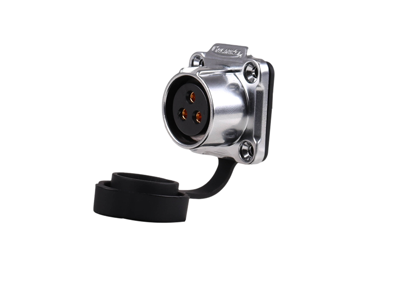
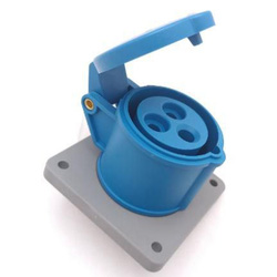
I have a sealey supermig welder and was looking at making the power cable removable when not in use. Normally I'd expect to use a blue commando socket but in this application it's not going to fit the case so I was thinking about using a c20 iec connector with the male socket mounted on the welder.

The power rating for the welder from the case is as follows, 230v 220 - 240v, 1~50/60hz fuse T16A.

It's currently wired to a 13a plug and I've never had an issue with it.

I can't see a reason why the 20a iec connector wouldn't work but I asked this question on a welding forum and they seemed to think it would be an issue and iec connectors aren't for constant use even if overspecced.

Thanks
Chris.
 
20a iec connector wouldn't work
C20 connectors and the other half which is a C19 are rated 16 amps, not 20.

If the welder is a maximum of 16A then theoretically it would be suitable, however the situations in which a welder is likely to be used are probably not the place where a C20/19 type of connector is suitable.
 
why isn't a c20 suitable for 20a when advertised as such?
Only rated to 20A in the USA where they use UL ratings - a system where a sample is sent for testing and when that passes some arbitrary test, the rest of the batch of 100000 items also magically complies.
Those connectors and the cables attached to them are 16A everywhere else that uses IEC standards.

unsuitable in the situations a welder may be used in?
That entire series of connectors is intended for indoor use with office equipment, computers and similar, which is certainly not where a welder would be used.
The standard is titled 'Appliance couplers for household and similar general purposes' , summary here: https://knowledge.bsigroup.com/prod...milar-general-purposes-general-requirements-4
 
Couldn’t you use inline commando sockets?
Ok you’d have a tail but if you cut the fixed mains lead long enough to sit the join on the ground, the unit will still be portable yet extendable
 
Would something like the below be more suitable then?
That particular connector is totally unsuitable for use a mains inlet because it has pins on the cable connector, and holes on the chassis connector. For an inlet you need the pins to be on the chassis connector and the holes to be on the same cable connector.

Beyond that there are several major downsides to using generic connectors, not explicitly designed to be mains connectors as mains connectors, even if their voltage and current ratings are sufficient.

1. Different people may use the same connector for different applications, leading to potential misconnection hazards.
2. There is typically no standard wiring, just numbered pins, so two people may select the same connector for the same application and still wire it differently.
3. Not all connectors are rated for safe disconnection under load. Sure you tell yourself you will switch-off, or unplug the other end first but will you always do so.
4. Not all connectors are touch-safe when unmated. Some are obviously not touch-safe when unmated but on others it may be less obvious.
5. The polarising features on the connector may not be particularly robust.

That's not to say it's something you should never do, but I would always try and use a purpose-designed mains connector where possible.

If you want a small waterproof, locking connector that is explicitly designed as a mains connector that can be disconnected under load then you might want to look at the "true 1 TOP" connector from Neutrik, but you should still be aware that it will not be as robust as a ceeform. You should also be aware that the original version had an issue where abused connectors could be mis-mated, later production added additional polarising features but I would still treat the connector gently.
 
Are you guys missing that the OP said that it already uses a 13A plug on the end of the existing cable?

Also there the IEC cables generally have a female connector on the end, a rewireable one with the existing cable will need to be used and not a generic IEC lead as the internal wires are too thin.

The one linked says it's 16A rated, however what would you do on the rear?
If you use crimp connector - are they rated as high?
 
Last edited:
I will confirm the IEC C19/20 connectors are totally not suitable for your application nor the metal connector and additionally I'll also say the True 1 is not robust enough for typical welding usage.

Going back to the beginning, IIRC this is a fairly big box on wheels sort of 1/8th of a cubic yard size, couple of switches, a speed control and the various cables on one side, lift off cover for the reel.
Can you really not fit a comando inlet on it?

I will say it's many many years since I've had to have any welding done on a car and not see one since then.

EDIT: I've just had a quick look and see there are a selection available. Which model do you have?
1773404558489.png
 
Last edited:
So I've been back into the garage having listened to what's been said.

IMG_20260313_133039.jpg


IMG_20260313_133455.jpg


That's my welder, looking at it again I suspect I can squeeze a commando inlet on the right between the wire feed knob and the 1/2 setting switch.

Ill need to get an inlet and see.

Thanks,
Chris.
 
Would this commando panel socket be suitable? Or should I go with a 32a panel socket, albeit I'd assume the 16a socket has been tested to have a safety margin over 16a?

 
You require an male or inlet, such as this panel mount
1773419547734.png
or this surface mount
1773419593983.png


Bear in mind when positioning it; the socket (AKA coupler) cover will have to open to 180º for the panel mount version and that space will have to be allowed for.
 
Sorry yes the widow maker principle.
It is only a "widow maker" if a live side can be accessed whilst live - that is if one of those shown is energised, if it is not live it needs to be plugged into a mating part to make it live.

In other words, any extension you use will only become a widow maker if you have a plug at both ends in order to plug one end in and the other end becomes live.
 
What are you going to do with the other end of the cable?
Keep it as is with the 13A plug on?

Guys, if it is supplied by a 13A plug, how can a 16A rated IEC socket be any worse?
As long as it's a C19 inline socket and a C20 chassis mount plug (or even an inline one) then they are high current and would certainly be upto the job.
Just cut the current supply cable 6" from the welder and add this:

Then put this on the cut end of the power cord:

Read the data sheet from Farnell.

Stop thinking of the nasty IEC cables that power a PC, Schurter are good quality industrial connectors.
I have seen 16A commando sockets that are much crappier than the above.
 

If you need to find a tradesperson to get your job done, please try our local search below, or if you are doing it yourself you can find suppliers local to you.

Select the supplier or trade you require, enter your location to begin your search.


Are you a trade or supplier? You can create your listing free at DIYnot Local

 
Back
Top