ADT Galaxy Upgrade - looking for suggestions

Hi all... right my panel is here and I want to make sure I'm prepared so as not to cause myself any issues regarding sirens, connections etc.

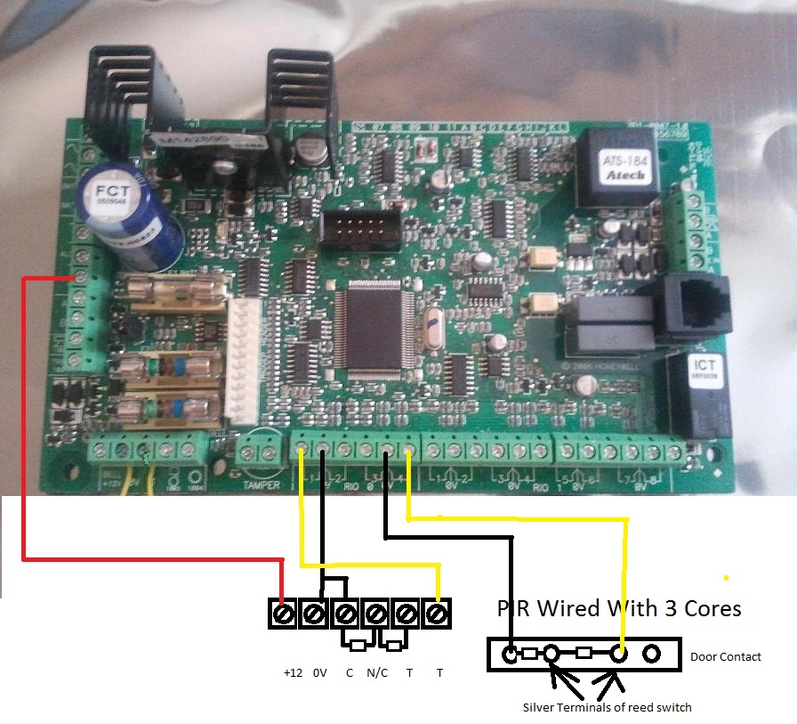
I've tried to show what I am planning in the pic below - the top board is existing and the bottom the new. Some reconnections seem obvious (? lol) others not so...

Comments on the plan and answers to the questions in the pic would be most appreciated! My aim is to get the hardware swapped and new panel connected so that it's ready for programming and will keep the siren from sounding.

Cheers in advance :)

Alarm Switch Over.png
 

Attachments

  • Alarm Switch Over.pdf
    369.8 KB · Views: 97
Sponsored Links
Looks like the Final and Exit Terminate maybe the other way round...?

Zones.PNG


i.e. Z1 Hall PIR and Z2 E/T doorbell?
 
Need 1 and 2 swapping over then, ta

am I barking up the right tree with the SAB and keypad connections?
 
Sponsored Links
Some additonal answers:


1.1. Yes
1.2. Yes
1.3. Bell goes to OP1. Strobe (if fitted) goes to OP2.
1.4. Use the +12 V on the vertical connector on the left for +Hold once you have finished wiring everything else.

2. Yes.

3.1 These are EOL, so there's 0V and the zone. Keep them like for like. There is no need for the resistors on the first zone as the Flex allows individual zones to be programmed N/C if required.
3.2 If you want to use the bell push for exit terminate, then yes, keep the same. I assume that's how you're setting at the moment ? Eg. Pressing the bell once you're all locked up.
3.3 You can get power from the +12V on the zones connections, or any other +12V point. They all join to the same copper tracks.

4. The speaker gets wired to +12V one terminal and OP3 on the second. If they are 16 ohm speakers, wire in parallel. If they are 8 ohm speakers wire in series.
 
Thanks GalaxyGuy! V helpful as ever!

We can't set the alarm at the min because of the line fault and it not on monitoring.

3.1... so remove the resistors and wire as is... i.e. door bell to Z1?
3.3... so I can wire the + from the detectors to the nearest +12v on the board got it... but what about the -v connections that are at the moment all wired in to a terminal and go to a -v on the existing board?
 
The center terminal of each pair of zones is 0v. So, it goes Z1, 0V, Z2, Etc. The sensors actually only need three cores, with the 0V on the power and also the zone, but people wire them with 4 wires due to legacy wiring.

See the PIR wiring at the bottom left of this image:

 
Ah right... I get it... nice one. Does it actually matter which way round the sensor wires are wired (I.e. blue and yellow)? And 0v has to be wired to 'c' in your diagram or can that be 'c' or 'T'?
Is it better practice in my situation to rewire each pir with c and 0v wired together or shall I simply connect them in the panel?
 
If the sensors have been wired with the zone wires separate from the sensor 0v supply (four wires), then no, it does not matter as there is no polarity - the sensor contacts are just switches that change the resistance of the zone circuit from 1k to 2k ohms depending on the sensor state.
If three wires have been used (doesn't look like it in your picture) , then it's important that the 0v is correct.
 
Last edited:
Sorry to keep after clarifications... see the terminal block... that has all the + & - wired to it.
The + I get.
The -'s... wire each one to the '0v' between the zones? So...
Z3&4 for example...
both red 12v to pin 12v
Pir Z3 yellow to pin 3
Pir Z4 yellow to pin 4
Blue and black wires from both pirs to 0v for those zones.
20200123_201215.jpg


Plus... any clues on what this is... two wires unlabeled wired together...
 

Attachments

  • 20200123_202923.jpg
    20200123_202923.jpg
    135.3 KB · Views: 79
So what's that do and where's it go to/from if it ain't wired into the panel!?
 
Check to see if your keypad or Rio has two cables going to it. It may be that the installer has the bus from a+b and power going to the device and then coming back to the panel casing and connecting to the other devices cable. Eg. From panel a+b to keypad and from keypad back to the panel where it's joined to a cable going to the Rio.

You can keep the sensor power wiring the same in the terminal block and just wire to the left hand vertical power connections. This will keep your zone wiring tidy at least and avoid the need for cramming four 0v wires in each panel terminal.
 

DIYnot Local

Staff member

If you need to find a tradesperson to get your job done, please try our local search below, or if you are doing it yourself you can find suppliers local to you.

Select the supplier or trade you require, enter your location to begin your search.


Are you a trade or supplier? You can create your listing free at DIYnot Local

 
Sponsored Links
Back
Top